Finding the Right Technology to Solve the Datacenter Power Challenge
Article
Digitization and the rapid deployment of cloud services have boosted the growth of datacenters worldwide. Datacenters consume close to one percent of global electricity, a number that is only expected to grow. Industry trends, such as metaverse and augmented and virtual reality, will continue to demand more energy than the planet can sustainably produce. While increasing renewable energy contribution is a step in the right direction, it is not enough, and energy efficiency is another area of focus that targets the nearly 40 percent of datacenter operational costs due to energy consumption by servers and their cooling systems.
Global standards for datacenter power supplies also continue to evolve toward higher efficiencies. The Open Compute Project (OCP) 3.0 offers further optimization of hardware that lowers energy consumption, and the 80 Plus Platinum and Titanium certification requirements as well as EU’s Ecodesign in Europe (ErP) Lot 9 regulations continue to evolve (Table 1). The next update to Lot 9 is already scheduled for January 2026.
| Efficiency | Power Factor | 80 Plus | |||||||||
|---|---|---|---|---|---|---|---|---|---|---|---|
| Requirement | Output/Load | 10% | 20% | 50% | 100% | 10% | 20% | 50% | 100% | 230 V non-redundant | 230 V redundant |
| Lot 9 (March 2020) | Multi | — | 88% | 92% | 88% | — | — | 0.90 | — | Gold | Gold |
| Single | — | 90% | 94% | 91% | — | — | 0.95 | — | Platinum* | Platinum | |
| Lot 9 (Jan. 2023) | Multi | — | 90% | 94% | 91% | — | — | 0.95 | — | Platinum* | Platinum |
| Single | 90% | 94% | 96% | 91% | — | — | 0.95 | — | Titanium | Titanium | |
Table 1: Lot 9 and 80plus have similar requirements with 80plus titanium applications demanding a >98.5% pfc peak efficiency
Power architecture evolution
As processor and server power is increasing, datacenters are using more power per rack. They now need 2-4 kW discreet blocks with the industry trending toward even higher power densities.i Distributing this power at the first-generation 12 V levels means having to handle much higher currents. To provide 1 kW to a server rack, the traditional 12-V architecture needs to deliver 83 A of current. To control I2R losses and address safety concerns, more copper would be needed in the wiring harness of such a system.
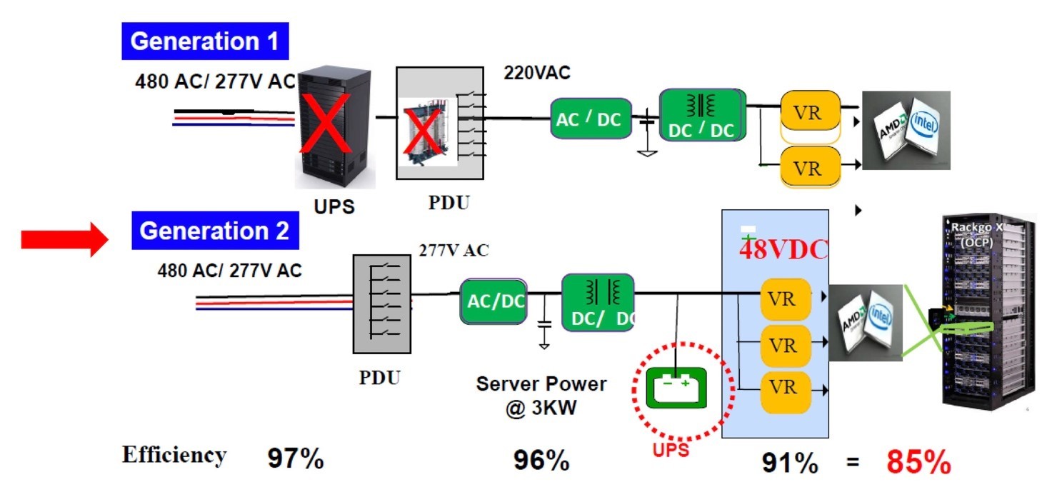
A one-percent efficiency improvement can result in saving kilowatts at datacenter level and second-generation power architectures, using 48 V (Figure 1), result in 16-times lower I2R losses while still being below the UL-60950-1 standard 60 V DC Safety Extra – Low Voltage (SELV) limit beyond which additional insulation, spacing, and testing are required. To meet new energy efficiency requirements, the enterprise datacenter power sector is therefore adopting a 48 V architecture.
Generation 2 rack systems, built out as discrete 2-4 kW power blocks, replace the massive high-voltage Uninterruptible Power Supply (UPS) and Power Distribution Units (PDUs) from Generation 1 with smaller UPSs per rack that are charged using a 48 V DC supply. The AC-DC and DC-DC supplies not only operate each server board but charge the UPS battery. The removal of load sharing and redundancy from Generation 1 leads to the requirement for each power supply to operate at close to full (100%) load.

Challenges to server PSUs
Apart from the challenges due to the changes discussed above, it is worth noting that the OCP 3.0, Open Rack V.2 (ORV) and Bitcoin/mining power supply units (PSUs) require a move beyond 2 kW to the 3-4 kW range. Rack manufacturers continue to call for small form factors and low profiles of 40 mm (height), high power density, effective and low-cost thermal management, and EMI design to manage the high-speed switching that reduces size of the magnetics. In addition, there is requirement for full digital control and design flexibility from using power MOSFETs mounted on a daughter card.
In considering semiconductor device technologies to solve these challenges, differences must be noted in terms of bandgap, critical electrical breakdown, electron mobility, and thermal conductivity, all of which affect the peak operating temperature, voltage, efficiency, and thermal management requirements of the system.
The semiconductor solution
Although silicon (Si) is the most familiar technology, its smaller bandgap limits operating temperature, its low breakdown electric field restricts its use to lower voltages, and its low thermal conductivity limits power density compared to wide bandgap materials, like gallium nitride (GaN) and Silicon Carbide (SiC).
For the efficiencies needed in datacenter power supplies, it is important to compare switching and conduction losses. Conduction loss, which is the device’s I2R loss, is lower when the ON drain-to-source resistance (RDS(ON)) is low and changes less with temperature.
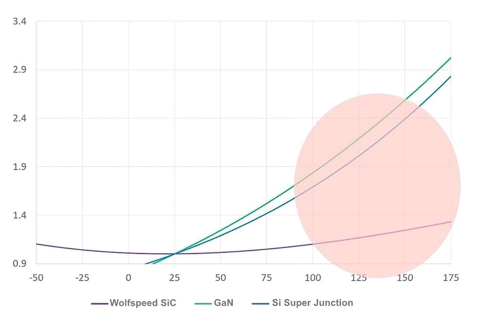
Figure 2 shows normalized RDS(ON) plotted against temperature for the technologies that many designers consider using to meet Gen 2 datacenter PSU requirements — SiC, GaN, and Si Super Junction (SJ). It is interesting to note that both GaN and SJ devices boast a lower RDS(ON) below 25°C, which are temperatures not quite practical for datacenter power supplies. As datasheets for GaN and SJ devices often specify RDS(ON) at 25°C, it can mislead engineers into assuming that specification at the much higher operating temperatures for which systems are normally designed.

Another interesting characteristic to note in Figure 2 is the change in RDS(ON) over temperature. SiC’s curve remains nearly flat, and although the other technologies both show a significant increase in RDS(ON), this change is particularly dramatic for GaN. Since designers have to use RDS(ON) at real-world junction temperatures of 120°C to 140°C, a 60-mΩ SiC device would be 80-mΩ “hot,” while a 40-mΩ Si SJ or GaN device would really be significantly >80-mΩ hot.
GaN’s low switching loss ≠ low total loss
GaN’s high electron mobility is the property that enables its well-known and unmatched efficiency at very high switching frequencies. Among the technologies discussed here, GaN offers the lowest switching loss (Figure 3).
Wolfspeed compared their 60-mΩ SiC device with a 50-mΩ GaN device in a totem pole PFC simulation to find that although GaN had slightly lower switching losses over the entire power range, any gains were offset by the increased conduction losses with power and consequently junction temperature increase. This requires GaN devices to be made oversized to compensate for higher conduction losses regardless of switching frequency.
The GaN testing had to be stopped at 3 kW due to power limitations of the device. The study clearly demonstrated that SiC results in significantly lower total losses, especially at the high power levels at which wide bandgap semiconductor use is most compelling, such in as datacenters. The various device-level performance specs of the three semiconductor technologies are compared in the radar chart in Figure 4.
At first glance, we notice GaN’s benefits are the lowest reverse recovery charge Qrr for the lowest switching loss in continuous conduction mode (CCM) synchronized rectifier, the lowest time-related output capacitance Coss(tr) for low dead time, and high frequency and efficiency, and the lowest energy-related output capacitance Coss(er) for minimum switching loss in hard-switched topologies. Notice that SiC trails close behind GaN in these attributes, while Si lags significantly.
Silicon wins include the lowest junction-to-case thermal resistance Rthjc, which confers better thermal performance, and the highest threshold voltage Vth, which offers better immunity to noise and makes Si devices easier to drive. Note that GaN has an extremely low Vth.
The maximum junction Tj_max and the avalanche energy, single pulse Eas indicate device robustness. SiC is the most robust as shown, while GaN has no Eas capability. SiC also has the lowest RDS(ON) change over temperature, which results in low conduction loss at high temperature. This is where GaN lags considerably to undo all gains from low switching loss.
Put together, SiC’s strengths help deliver the highest efficiency at higher power levels, as well as high power densities required for enterprise datacenters and similarly demanding applications.
The package point of view
Since Wolfspeed developed the SiC technology for a successful transition from Si, many of the common surface-mount and through-hole packages are available for SiC products. GaN, on the other hand, faces unique challenges toward package standardization.
For instance, GaN through-hole packaging is uncommon because products need to have lower parasitics and allow very-high-frequency switching to best utilize the material’s strengths. GaN is often either offered in large QFN or custom packages. Large QFN suffers from board-level reliability concerns and custom packages lack multisource availability as well as tooling capability at subcontractors.
GaN’s power device package challenges do not end here. Other common concerns include:
- Kelvin source pins, widely adopted in SiC for better switching control, are not feasible in cascode GaN since other internal parameters like the cascode FET and capacitances go unaccounted. The common source cannot be eliminated and the cascode GaN is limited to TO-247-3 (three-lead) package in which the vulnerability to gate oscillation limits switching speeds.
- Some custom packages on the market are so thin, they constrain the space available for a heatsink.
- Another custom package on the market has a top-side cooled drain, which requires thermal interface materials (TIMs) with high thermal conductivity to extract heat away from the device.
- Yet another TO-Leadless (TOLL) package for GaN places the gate and the Kelvin source in a direction different from standard Si, which makes transition from the latter technology cumbersome.

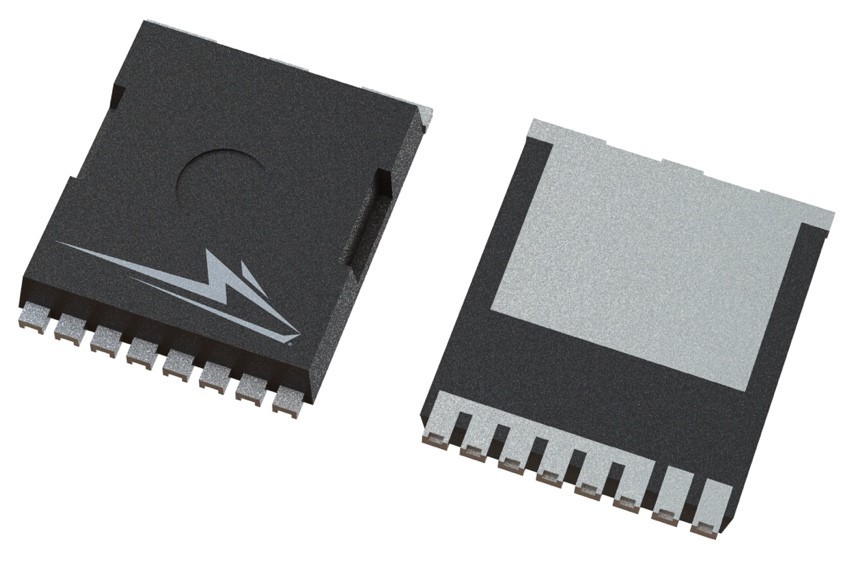
As the market moves towards high-power density design and tighter space constraints, the TO-Leadless (TOLL) package offers advantages of low height and smaller footprint, and its leadless form results in low lead inductances that would otherwise become a concern in high frequency operation. The package’s larger drain tab area addresses thermal performance concerns from small packages.
TOLL is a relatively new package for the datacenter and server power supply market. Wolfspeed is, however, supporting that market with product development in this direction, such as with new TOLL package variants for datacenter and server power.
A system-level comparison
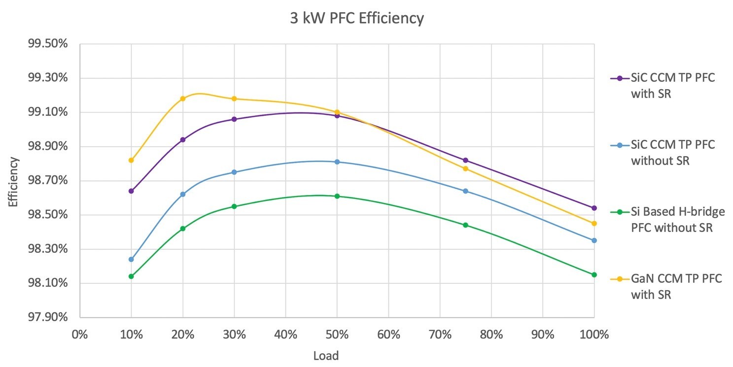
Compared with Si-based H-bridge, SiC-based CCM totem pole PFC can have not only higher efficiency but higher power density at similar or lower cost.ii A comparison of efficiency between technologies clearly shows that while both SiC- and GaN-based CCM totem pole PFCs can achieve >99% efficiency, GaN has the efficiency advantage only at very light loads. As discussed earlier, GaN’s much higher RDS(ON) change over temperature (Figure 2) results in its dramatically drooping efficiency curve at higher power/loads. In applications, like datacenters, that operate at or near full load 24/7, GaN therefore fails to meet efficiency requirements.
SiC, on the other hand, provides an efficiency similar to that of GaN at half load and better efficiency at full load (Figure 5).

Taking a broader look to include power density, the number of components, and relative cost of SiC- and GaN-based CCM totem pole PFC (Table 2), it is noted that SiC is better than GaN not only in terms of efficiency in high-power density applications, but also in terms of gate drive complexity, control, and cost.
# PFC Choke | # Power Semiconductor | Power Density | Peak Efficiency | Cost | # Control | # Gate Drive | |
|---|---|---|---|---|---|---|---|
SiC CCM Totem Pole Semi-BL PFC | 1 | 4 | Highest | 98.8% | Medium | 2 | 2 |
SiC CCM Totem Pole bridgeless PFC | 1 | 4 | Highest | 99.1% | High | 3 | 3 |
GaN CCM Totem Pole Semi-BL PFC | 1 | 4 | Highest | 98.8% | High | 2 | 3 |
GaN CCM Totem Pole bridgeless PFC | 1 | 4 | Highest | 99.2% | Highest | 3 | 4 |
GaN CRM Totem Pole bridgeless PFC | 2 | 6 | Medium | 99.1% | Highest | 4 | 5 |
Table 2: Topology and component analysis of Silicon Carbide- and GaN-based bridgeless PFCs.
In yet another comparison of real-word wide-bandgap demonstrator designs from various companies, Wolfspeed SiC shows clear advantages (Table 3). Some key points to note are:
- Many of the existing reference designs require impractical thermal management and restrict design flexibility.
- GaN FET-based totem-pole designs have lower efficiency at full load due to the high temperature coefficient of RDS(ON).
- As expected, SiC’s low temperature coefficient of RDS(ON) results Wolfspeed’s design to exhibit a nearly flat efficiency curve from half load to full load.
- While SiC and GaN meet requirements for bridgeless PFCs in the 2-4 kW range, high conduction losses make GaN thermal design challenging beyond 4 kW.
- System frequencies of the reference designs are limited to the 45-47 kHz and 60-67 kHz ranges to keep harmonics under 150 kHz for CE’s EMI requirements. This negates GaN’s advantage from low switching losses.
Peak Efficiency | Full-Load Efficiency | HF Switch | LF Switch | Height (mm) | Power Density (W/in3) | Efficiency Standard | Physical Standard | Comments | |
|---|---|---|---|---|---|---|---|---|---|
Company A 2.6kW | 99.14% | 98.7% | GS66516B 32mΩ GaN | IXFH60N65X2 | 40 | 78 | 80+ Titanium/ ErP Lot9 | None | SMD GaN |
Company B 2.5kW | 99.2% | 98.5% | IGO60R070D1 70mΩ GaN | IPT65R033G7 | 45 | / | 80+ Titanium/ ErP Lot9 | None | eGaN, limited to 2.5kW by 70 mΩ |
Company B 3kW | 98.9% (50% load) | 98.5% | IMZA65R048M1H 65mΩ GaN | IPW60R017C7 (SJ MOS) | 40 | 32 | 80+ Titanium/ ErP Lot9 | OCPv3 | PFC SiC primary & Si secondary, LLC Si. No daughter card. |
Company C 4kW | 99% | 98.55% | GAN041-650WSA 41mΩ GaN | STY139N65M5 | 50 | / | 80+ Titanium/ ErP Lot9 | None | Cascode GaN |
Company D 3.6kW | 97.7% | 97.1% | SCTW35N65G2V 55mΩ GaN | TN3050H-12GY | 57 | / | 80+ Titanium/ ErP Lot9 | None | SiC, SCR, low efficiency |
Company E 4kW | 98.73% | 98.57% | LMG3410R050 50mΩ GaN | STY139N65M5 | 35 | 123 | 80+ Titanium/ ErP Lot9 | None | GaN, Interleaved, switching at 115 kHz (in CE bnad=nd)=) |
Company F 3.3kW | 99% | 98.55% | TP65H050WS 50mΩ GaN | STY139N65M5 | 50 | / | / | None | Cascode GaN |
Wolfspeed 2.2 kW | 98.79% | 98.68% | C3M0060065J/K 60mΩ GaN | FRED diode | 64 | 20 | 80+ Titanium/ ErP Lot9 | None | SiC, no SR |
Wolfspeed 3.6 kW | >99% (50% load) | >98.5% | C3M0045065L 45mΩ SiC TOLL | VS3CDU06H (diode) | 40 | 92 | 80+ Titanium/ ErP Lot9 | OCPv3 | SiC primary with SR option, daughter card concept |
Table 3: A competitive analysis of wide bandgap reference designs on the market.
Wolfspeed’s 3.6 kW solution
Wolfspeed’s new 3.6 kW totem-pole PFC reference design (Table 3, last row) is aimed at solving the datacenter and server power supply challenge with >99% efficiency at half load and >98.5% full load, achieving 80 Plus Titanium and ErP Lot 9 requirements.
4 x MOSFETs | 2 x MOSFETs in HF leg + 2 x Diodes in LF leg | |
|---|---|---|
MOSFET cost % | 55.6% | 27.8% |
Diode cost % | 0.0% | 8.7% |
Gate drive cost % | 37.0% | 18.5% |
PCB, Heatsink | 3.7% | 3.7% |
Assembly cost | 3.7% | 3.7% |
Efficiency @ 50% | 99.1% | 98.6% |
Efficiency @ 100% | 98.9% | 98.5% |
Total cost 100% | 100.0% | 62.4% |
Table 4: The efficiency and cost comparison of four- and two-MOSFET options available for Wolfspeed’s 3.6 kW design.
The design also offers the flexibility to tradeoff some of the high efficiency for lower cost, while still meeting the efficiency standards mentioned above (Table 4). The lower cost option replaces two of the MOSFETs in the low-frequency (LF) leg of the design with diodes, while retaining them in the high-frequency (HF) leg.
A two-daughter-card design concept gives customers the flexibility to choose the right option depending on their system design priorities.
In developing such solutions, Wolfspeed uses its extensive experience building a broad portfolio of the most field-tested SiC and GaN on SiC solutions on the market. With a semiconductor team that best understands the strengths and future potential of both technologies, Wolfspeed is uniquely qualified to target the technology most suited to any given application.
Visit our website to find out more about the Wolfspeed 3.6kW Totem Pole PFC Reference Design.
i WiWynn Corp., et al, 48V: An Improved Power Delivery System for Datacenters (https://www.wiwynn.com/whitepapers/48v-an-improved-power-delivery-system-for-data-centers)
ii Wolfspeed, et al, Silicon Carbide Enables PFC Evolution, Aug. 17, 2020 (https://www.wolfspeed.com/knowledge-center/article/silicon-carbide-enables-pfc-evolution/)