Introducing EAB450M12XM3: Wolfspeed’s first Automotive-Qualified Silicon Carbide Power Module
Article
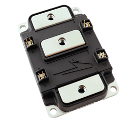
Many markets today are benefiting from the advantages of Silicon Carbide (SiC) technology, especially the automotive industry. With SiC’s performance improvements over traditional silicon (Si)-based components, systems are seeing lower power losses, faster switching, higher operating temperatures, greater power density, and overall much higher efficiency. Wolfspeed’s portfolio of SiC devices spans a wide range of power levels and applications that bridge the power continuum between lower-power, discrete-based applications through both familiar, industry-standard footprints as well as optimized footprints in higher-power modules. The newest member added to the high-power module family of devices is the EAB450M12XM3 (seen below in Figure 1).
Wolfspeed’s power module product line (shown in Figure 2) includes WolfPACK modules that provide a baseplate-less, industry-standard footprint with up to 1.2kV and 200A operation, while the higher-power modules come in more optimized packaging and serve more demanding applications. All of the modules in this portfolio aim to achieve the same goal of maximizing power density, simplifying layout/assembly, enabling scalable systems and platforms, and minimizing costs of labor and system components while providing the highest level of reliability.

Module Type | Wolfspeed WolfPACK™ | Leadframe with Baseplate | ||
|---|---|---|---|---|
Platform | FM/GM Industry Standard | BM Industry Standard | XM Wolfspeed Standard | HM Wolfspeed Standard |
MOSFET Gen | Gen 3 | Gen 2 / Gen 3 | Gen 3 | Gen 3 |
Voltage | 1.2 kV | 1.2 kV/1.7 kV | 1.2 kV/1.7 kV | 1.2 kV/1.7 kV |
Current | <200 A | <600 A | <500 A | <800 A |
Qual Level | Industrial | Industrial/harsh environment | Industrial / Automotive | Industrial |
Recommended Applications | PV, Energy Storage, Low Cost Industrial Apps, Off-Board Charger | Rail Aux Power, Broad Industrial | Heavy Equipment/Performance Drivetrain Inverter, UPS, Off-Board Charger | Test Equipment, Fast Charging Off-Board Chargers |
The XM3 series
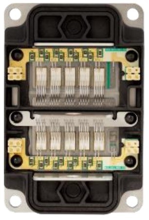
The XM3 half-bridge modules take advantage of SiC benefits while maintaining a simple, scalable, and cost-effective footprint that is half the weight and volume of the industry-standard 62-mm counterpart. These XM3 modules maximize power density while minimizing loop inductance and switching losses. In addition, they have low-inductance bus bar interconnections, integrated temperature sensors, built-in voltage sensing, and a high-reliability power substrate with enhanced power-cycling capabilities. The package enables 175˚C continuous junction temperature with a high-reliability silicon nitride (SiN4) substrate to ensure mechanical robustness under extreme conditions. The housing has been designed for modularity and scalability in a number of configurations, all with inductance as low as 6.5 nH (which is up to 50% less inductance when compared with similar modules). This makes the XM3 a perfect fit for demanding, harsh conditions, as seen in automotive applications such as traction drives, DC fast chargers, and automotive test equipment. The SiC-optimized XM3 package enables a much more compact system when compared with similar power modules such as SemiTrans 3 or EconoDual, both of which feature similar voltage and current ratings (up to 450 A at 1,200 V). Figure 3 shows the top view of an opened XM3 half-bridge module.
EAB450M12XM3
Table 1 outlines the maximum parameters for the EAB450M12XM3 module (taken from the datasheet).
Symbol | Parameter | Min. | Typ. | Max. | Unit |
|---|---|---|---|---|---|
VDS max | Drain-Source Voltage | 1200 | V | ||
VGS max | Gate-Source Voltage, Maximum Value | -8 | +19 | V | |
VGS op | Gate-Source Voltage, Recommended Operating Value | -4 | +15 | V | |
IDS | DC Continuous Drain Current, TC = 25 °C | 450 | A | ||
IDS | DC Continuous Drain Current, TC = 90 °C | 409 | A | ||
ISD BD | DC Source-Drain Current (Body Diode), TC = 25 °C | 225 | A | ||
IDS pulsed | Maximum Pulsed Drain-Source Current | 900 | A | ||
TVJ op | Maximum Virtual Junction Temperature under Switching Conditions | -40 | 175 | °C |
Highlights include the 1200 VDS max 450A continuous drain current and 175˚C virtual junction temperature (during switching), all of which have been verified by design. A summary of the MOSFET characteristics (per position) can be seen below in Table 2.
Symbol | Parameter | Min. | Typ. | Max. | Unit. |
|---|---|---|---|---|---|
VBR DSS | Drain-Source Breakdown Voltage | 1200 | V | ||
VGS th | Gate Threshold Voltage | 1.8 | 2.5 | 3.6 | V |
IDSS | Zero Gate Voltage Drain Current | 5 | 500 | μA | |
IGSS | Gate-Source Leakage Current | 0.05 | 1.3 | μA | |
RDS on | Drain-Source On-State Resistance (MOSFET Only), TJ = 25 °C | 2.6 | 3.7 | mΩ | |
RDS on | Drain-Source On-State Resistance (MOSFET Only), TJ = 175 °C | 4.6 | mΩ | ||
gfs | Transconductance, TJ = 25 °C | 355 | S | ||
gfs | Transconductance, TJ = 175 °C | 360 | S | ||
EOn | Turn-On Switching Energy, Tj = 25°C Tj = 125°C Tj = 175°C | 11.0 11.7 13.0 | mJ | ||
EOff | Turn-Off Switching Energy, Tj = 25°C Tj = 125°C Tj = 175°C | 10.1 11.3 12.1 | mJ | ||
RG int | Internal Gate Resistance | 2.5 | Ω | ||
Ciss | Input Capacitance | 38 | nF | ||
Coss | Output Capacitance | 1.5 | nF | ||
Crss | Reverse Transfer Capacitance | 90 | pF | ||
QGS | Gate to Source Charge | 355 | nC | ||
QGD | Gate to Drain Charge | 500 | nC | ||
QG | Total Gate Charge | 1300 | nC | ||
RTH JC | FET Thermal Resistance, Junction to Case | 0.110 | 0.145 | °C/W |
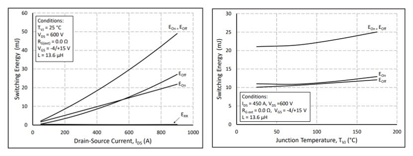
Notable parameters from the table above include a very low RDS(on) of 2.6 mΩ at 25˚C and a low junction-to-case thermal resistance of 0.110˚C/W. Figure 4 demonstrates the switching energy of the MOSFET. Note that even with higher junction temperatures, the switching energy remains fairly constant.
The MOSFET’s body diode features a forward voltage of 4.7 V with a 52-ns recovery time (see Figure 5 for a plot of the reverse-recovery performance and its low loss). This fast recovery time and low recovery loss greatly help improve the performance of the MOSFET during switching.

The built-in NTC temperature sensor has 4.7 kΩ of rated resistance with a ±1% tolerance (ΔR/R), providing high-level temperature protection with reasonable accuracy. Thermal monitoring can be essential to achieving high reliability, so having this real-time feedback can help the designer optimize control techniques.
Additionally, a dedicated Kelvin-drain pin enables direct voltage sensing for gate driver overcurrent protection, which greatly reduces error due to stray inductance and thus additional voltage during high switching speeds.
Schematic, pinout, and performance plots
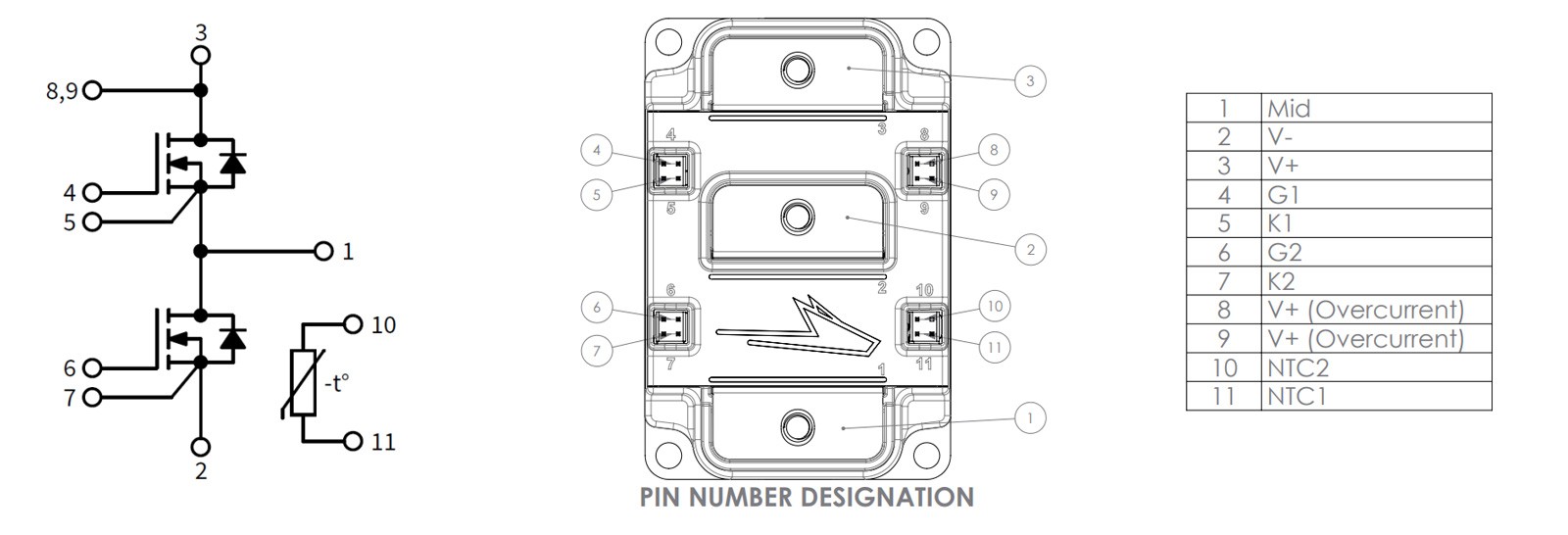
Figure 6 indicates the internal wiring of the EAB450M12XM3.
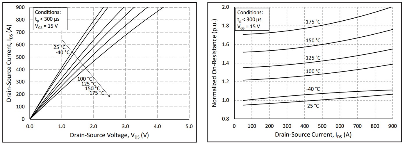
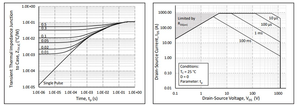
Figures 7 and 8 indicate some of the performance characteristics associated with the EAB450M12XM3. The output characteristics shown in Figure 7 demonstrate how VDS and RDS(on) increase when running at higher junction temperatures, and display the low RDS(on) temperature coefficient of Wolfspeed’s third generation SiC MOSFET technology. Figure 8 illustrates the transient thermal impedance and the forward bias safe operating area. It’s important to manage the temperature of this module with proper mounting and cooling, as seen in the application note CPWR-AN29. Additionally, the CRD300DA12E-XM3 and CRD600DA12E-XM3 reference designs, which feature three of the EAB450M12XM3 modules, demonstrates a complete, optimized stack-up including modules, cooling, bussing, gate drivers, voltage/current sensors, and controller. Many more performance and timing plots can be viewed in the module’s datasheet.
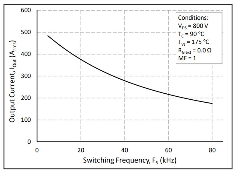
Lastly, Figure 9 shows the relationship between ampacity (output current) and switching frequency for an inverter application.
Reference designs and supporting tools
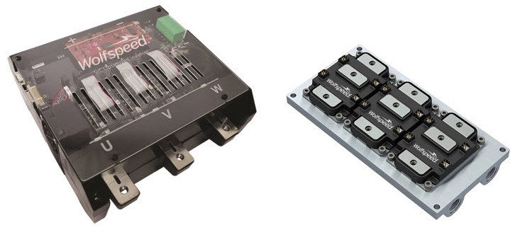
The CRD300DA12E-XM3 300 kW High Performance 3-Phase Inverter with a power density of 32 kW/L [CRD300DA12E-XM3] (Figure 10) is a great reference design to help get started with implementing a three-phase configuration that can be applied to a variety of applications. It provides many of the benefits seen with the XM3 series of modules, including compact/low weight, increased power density, high efficiency/switching operation, ultra-low losses, and reduced thermal requirements, all at a reduced system-level cost. The design has a DC bus voltage of 800 V (900 V max) with 360-A current. Additionally, a Wieland MicroCool CP3012-XP cold plate (also shown in Figure 10) is included for thermal management (and lowers the junction’s thermal resistance), which has been optimized specifically for the high heat flux of SiC.
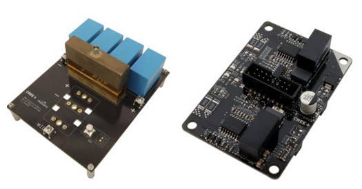
KIT-CRD-CIL12N-XM3 (Figure 11) is an evaluation platform that allows designers to accurately measure the voltage and current waveforms of Wolfspeed XM3 Power Modules under an inductive load switching event. This enables the calculation of switching loss energies under precise test conditions to dynamically evaluate the module and facilitate in-module comparisons. It’s corresponding gate driver (also shown in Figure 11) is a direct mount, dual-channel isolated gate driver optimized specifically for the XM3 power module.
Furthermore, the SpeedFit 2.0 Design Simulator helps to accelerate the design process with simulation results based on calculated losses, estimated junction temperatures, and lab data for common topologies ranging from simple buck/boost converters up to fully bidirectional totem-pole PFC designs. This helps to verify the right modules/components for an application while providing a real comparative performance for different devices and configurations.
Summary
To conclude, the EAB450M12XM3 automotive-qualified half-bridge all-SiC module includes a high-power-density footprint with optimized thermal management features that meet a variety of applications, such as motor and traction drives, vehicle fast chargers, and automotive test equipment. The designer gets the benefits of SiC (high switching frequency, low loss, increased power and temperature ratings, and better efficiency and reliability) in an easy-to-use housing that offers a terminal layout for direct bus bar connection without bends or bushings, enabling a simple, low-inductance design. Additional automotive grade components mating to the EAB450M12XM3 can be found by contacting the new Power Applications Forum. In addition, several reference designs, application notes, and design resources like simulators are available to help accelerate development and build confidence for the designer. Visit Wolfspeed’s website to learn more about the XM3 power module, access reference designs, and the new Power Applications Forum.