What’s Under the Hood? DC Fast Chargers: Delivering Rapid Top-Ups for EVs
Article
If the EV charging infrastructure required waiting in long lines for hours, there would be no market for EVs. Thanks to public charge points that are trending toward increasing power delivery for ever shorter charge times, EVs are finding avid buyers. Moreover, the supporting charging infrastructure is expanding rapidly — the global EV fast-charging system market could reach $10.82 billion by 2031, growing with a CAGR of nearly 16.6% during 2022-2031.1
There are two ways to charge an EV — via a Level 1 or 2 AC on-board charger (OBC), often overnight at home or via a DC fast charger (DCFC). In AC charging, the OBC converts the AC to DC in the vehicle but with DC fast charging, the conversion takes place in the charging station. DCFCs can reduce charge times down to anywhere between 15 and 45 minutes for an 80% top-up. This does impact battery life, however, such ultra-fast charging is generally recommended for commercial vehicles with large battery packs or smaller EVs on long road trips.
In this final chapter of Wolfspeed’s What’s Under the Hood series explore DC fast chargers, their power characteristics, architecture, communications, and interoperability.
Fast charger functionality
The DCFC delivers power at Level 3 (L3), the highest charger power level discussed in the article on charger standards.2 DC fast charging bypasses the OBC to charge the battery directly and significantly reduce the time it takes to charge the EV. However, the OBC is still the “brains” of the charging operation that monitors and communicates with the fast charger the battery pack charge and system status, and handles protection triggers.
The fast chargers host connectors that are compliant with one or more standards or proprietary specifications — CCS, CHAdeMO, GB/T, and Tesla2 — and output about 200 VDC and up to the 900
-1000 VDC range to support a wide range of vehicles, including both hybrids and battery EVs (BEVs). The DCFCs take as input three-phase 400-600 VAC and, as such, are not meant for home use where the available single-phase AC at a lower voltage cannot support the targeted L3 output levels.
Today’s DCFCs are available in broadly two types of implementations.
- Standalone: With the entire charger circuit and functionality from grid to vehicle in one box, these chargers output 50-250 kW of DC power. These units are fed directly by the medium voltage (MV) lines from the substation.
- Split: Sectioned into two as user unit and power as well as communications unit, the chargers deliver 175-350 kW to the vehicle. The user unit is fed over a [relatively] low-voltage (LV) DC bus from the power unit. The split charger allows the use of a large galvanic isolation transformer between the power unit and the MV line from the substation. The benefits are potentially lower noise and more available space at the user unit area.
High-level architecture
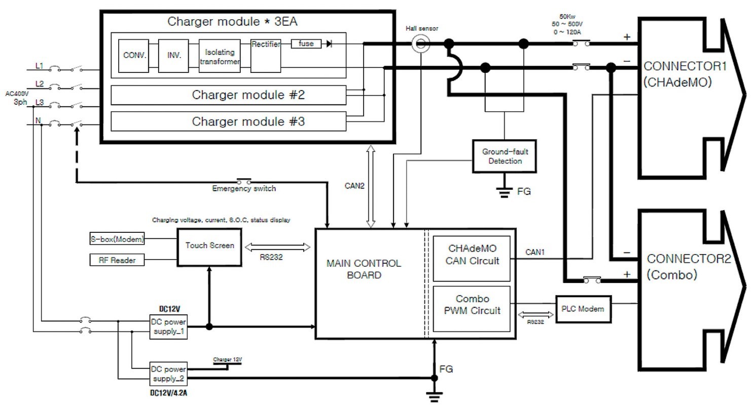
There is significant customization in DCFC designs and there are probably as many architectures as there are charger brands (Figure 2).3 However, the basic architecture for all includes a three-phase PFC, DC-DC converter, and a digital controller — similar to the OBC architecture discussed in that tutorial.4 Other features typical in DCFCs include protection mechanisms such as ground-fault detection shown in Figure 2, connections to the network, and various user and mechanical functions.

The overall design is modular with “power blocks” paralleled to achieve the power levels desired. Each block is typically 100-120 kW and includes the PFC and isolated DC-DC, such as with an interleaved LLC circuit topology. This allows power savings by allowing selective turning ON and OFF of blocks to meet the output desired at any time.
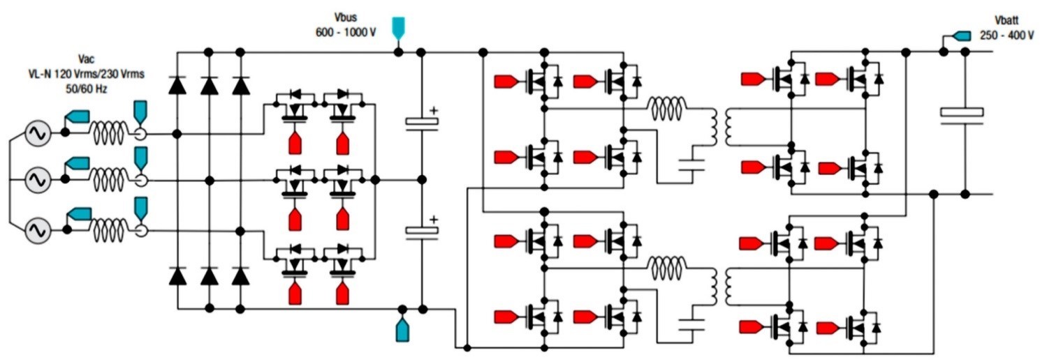
Common topologies used for three-phase PFC are totem pole and Vienna (Figure 3) with the latter becoming the most popular because it allows for three-level switching that offers three distinct advantages. First, only half of the total output voltage is applied to the switches used in the circuit, resulting in lower switching losses. Second, the peak-to-peak voltage applied to the inductor is half the total output voltage leading to less current ripple, smaller inductors, and lower cost. Third, lower peak-to-peak switching voltages and currents means lower radiated EMI. Overall, this spells higher efficiency, lower voltage stress on components, and higher power density.
The DC-DC converter is unidirectional, typically using a full-bridge LLC resonant topology (Figure 3) because DCFCs are not used to back-power the grid. The LLC circuit is interleaved to get higher power output per module. A single module, for example, might deliver 100 kW with 200 ARMS at 400 V or 125 ARMS at 800 V. Stacked with power modules, as shown in Figure 2, the charger block could then achieve much higher output — for example, 350 kW with 875 ARMS at 400 V or 438 ARMS at 800 V.

Communications & interoperability
DCFCs need to inform central management systems (CMS) of their status and charge tracked for customer billing, and enable customer authentication and access, dynamic load management of the power grid, charge station remote control, as well as remote firmware updates. While communication between EVs and charging stations is handled over IEC 61851 protocol, DCFCs use the Open Charge Point Protocol (OCPP) to talk to the CMS.
The OCPP, established in 2009 by the Open Charge Point Alliance, is used by EV Supply Equipment (EVSE) from over 40 manufacturers. An OCPP-compliant charging station can be networked through any available provider, wired or wireless. This network agnosticism allows for changing/upgrading of DCFC communication backbone with minimal disruption and at low cost. For example, charging locations typically prefer 4G and 5G cellular networks over the more cumbersome wired networks.
This interoperability forces the charging station manufacturers and network providers to compete on price, functionality and service, and innovation.
Conclusion
While the number of EVs on the road per public charging point globally rose to 9.2 at the end of 2021, this ratio is likely to continue growing and make it worthwhile for charging operators to install more fast chargers.5 There is already a wide variety of DCFC architectures, with many models offering multiple connector options, network-agnostic communication with the central management system, and up to 350 kW output for 80% charge top-ups within minutes.
To find more information on EV application trends and Wolfspeed’s power solutions, visit the Automotive Applications Page.
References
- ResearchAndMarkets.com, 2022, Electric Vehicle Fast-Charging System Market (https://www.researchandmarkets.com/reports/5567756/electric-vehicle-fast-charging-system-market-a)
- Wolfspeed, 2022, EV Chargers: A Tale of Standards and Many Connectors
- Signet Systems Inc., EV DC FAST CHARGER Manual FC50K-CC-S
- Wolfspeed, 2022, Onboard Chargers: Filling Up The Electric Ride
- BNEF, 2022, Electric Vehicle Growth Outpaces Installation of Battery Chargers (https://www.bloomberg.com/news/articles/2022-04-12/electric-vehicle-growth-outpaces-battery-charger-installations)