What’s Under the Hood? Onboard Chargers: Filling Up The Electric Ride
Article
The electrification of transportation is built on innovative developments, not just in battery technology and fast chargers, but also in on-board chargers (OBCs) that support up to Level 2 charging from ever smaller, lighter, cooler, and cheaper solutions.
In this chapter of Wolfspeed’s What’s Under the Hood series, shine a light on OBC functionality, architecture, and learn how they are so important to maintaining battery health.
The OBC’s job
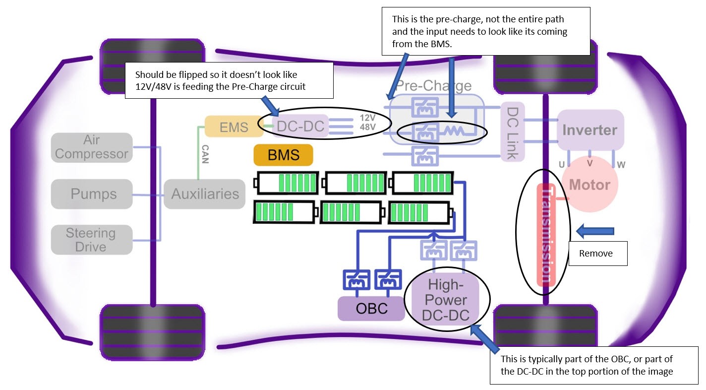
The OBC (Figure 1) handles the critical function of charging the high-voltage (HV) DC battery pack from an infrastructure power grid when an EV connects to a Level 1 or Level 2 wall outlet or electric vehicle supply equipment (EVSE) with a suitable cable. Simple as it seems, there’s more to this functionality:
- Power conversion: The OBC takes Level 1 or 2 AC input, converts it to DC and outputs the appropriate voltage and current. Depending on the EV battery pack architecture, the DC output may be anywhere between 200 VDC and over 900 VDC. The OBC delivers 1.3-19.2 kW for single-phase AC home charging or 11-22 kW for multiphase AC such as in commercial charging. Additionally, there is a trend toward bidirectional OBCs so that EVs can act as energy storage systems (ESS) for home or back-power the grid.
- Communication: The OBC is responsible for communicating the battery’s remaining charge status, any faults in the system, and the plug-in/ongoing charging status. This communication is important, for instance, to disable EV traction while the vehicle is plugged in.
- Li-ion charging profile: The charger handles the battery pack’s charge profile that may comprise 3-4 stages. The OBC monitors the charge being delivered by measuring the current flowing to the battery pack or, in the case of bidirectional functionality, to the grid.
Li-ion charge profile
The OBC controls the current and voltage at which the battery is charged to extend battery lifespan. This is done by offering either constant current or constant voltage charging, depending on the charge state of the battery.
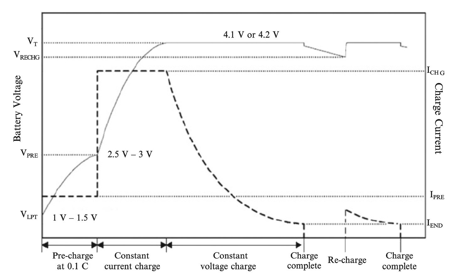
As shown in Figure 2, a typical Li-Ion charging profile1 comprises modes that correspond to charge states:
- Pre-charge: This pseudo-healing mode allows for recovery of the passivation layer that may dissolve when the battery stays for long in a deeply discharged state. In this mode, the OBC charges the battery at a low C-rate, typically 0.1C at a specified current of IPRE, until the cell voltage reaches the threshold VPRE of 2.5-3 V.
- Constant current: This fast charge mode uses constant current regulation, usually at 0.5C to 1C (ICHG) and contributes to most of the cell charge.
- Constant voltage: To avoid the risk of overcharging, which would reduce battery life, the OBC enters a constant voltage regulation stage close to the peak cell voltage of 4.2 V. The battery is usually 65-70% charged at this point and current begins to taper off at fixed voltage.
- Charge termination: When charging enters its completion mode, current delivered into the battery pack (IEND) is decreased to 3-5% of the rated capacity (Ah) or 0.02C and charge delivery is eventually stopped to avoid overcharging.
- Recharge: When the battery voltage drops, from system use or from a long period of disuse, and reaches a recharge threshold voltage, VRECHG, a “top-up” charge is started.
OBC architecture
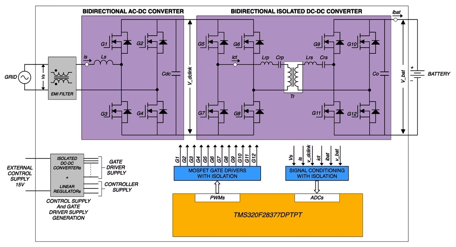
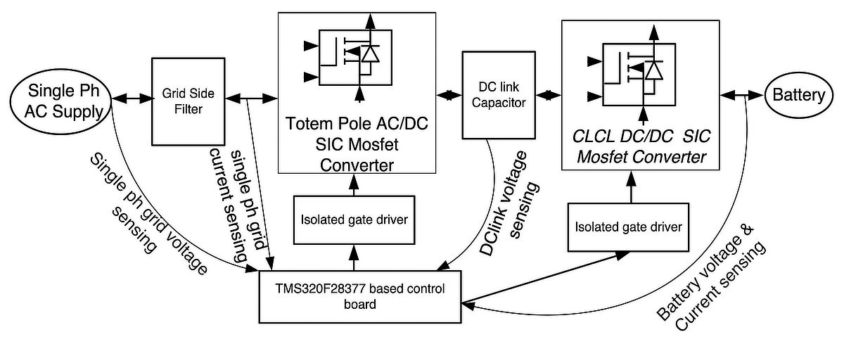
The key components of the OBC include an AC-DC rectifier that may be integrated with a single- or three-phase power factor correction (PFC) stage that ensures real power, as opposed to reactive power, is passed to the battery. After this an isolated DC-DC converter, which typically uses a resonant architecture and soft switching for lower losses, provides the isolation and a controllable voltage source. A microntroller offers the control necessary to handle the complex requirements of the charging profile, faults, and communication (Figure 3).
Let us take a closer look at these components.
Power factor corrector
The PFC stage is often integrated into the input stage that comprises an EMI filter, a full-bridge, bridgeless, or totem pole rectifier, and one or more capacitors; parallel-connected capacitors being the main components handling PFC. But why is it important?
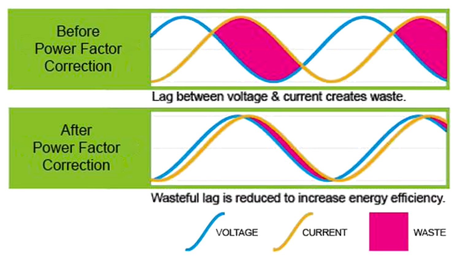
AC voltage and current are sinusoidal and change continuously in both magnitude and direction. AC power at any instant is given by the product of the voltage and current at exactly that instant. Reactive components in an AC circuit, cause the voltage and current to go "out of sync." (Figure 4).
This means that significantly more current is delivered during a low voltage part of each AC cycle. Therefore, even as low "real" power is being transferred, the circuit must carry large currents to deliver reactive power that is given back by the load in the next cycle. For instance, a 120 V outlet delivering 12 A at 50% reactive power (PFC = 0.5), delivers real power of just 720 W instead of 1.44 kW. This reactive power can also cause excess heating in the system that is avoidable and could lead to thermal issues.
The full-bridge rectifier, the smoothing capacitor, and capacitive and inductive loading on the DC output cause high reactive power. Active PFC uses a boost converter to align the current and voltage waveforms with the help of an inductor. Designers choose from one of several topologies – full-bridge boost, bridgeless for lower losses by avoiding the input diode bridge, totem pole with or without diodes, and interleaved to accommodate multiple phases for higher power.
Modes of operation to control the current include:
- Continuous Conduction Mode (CCM): It is the most common for high-power applications, like the OBC. It continuously passes current to a switching reactor, the inductor.
- Transition Mode (TM): Also called Critical Conduction Mode (CrCM or CRM), it allows the inductor current to reach 0 A. It employs zero current switching (ZCS).
- Discontinuous Conduction Mode (DCM): Current drops to 0 A and remains off for a certain interval. However, it requires higher peak currents.
Bidirectional DC-DC
The DC-DC converter offers a controlled output to the HV battery. Its topology is typically a resonant converter with soft switching to reduce losses. Bidirectionality is often implemented using the CLLC topology. The output voltage and current can change with switching frequency as the latter affects gain. A high-frequency transformer offers galvanic isolation between the DC-DC output and the AC wall source so as to protect against voltage spikes during fault events. Designers prefer to use higher switching frequency so that they can use a smaller, lighter high-frequency transformer.

The soft switching benefits over hard switching are shown in Figure 5. With soft switching, zero voltage (ZVS) and zero current switching (ZCS) can be achieved to ensure that voltage or current across the MOSFET are zero when it is turned ON or OFF. This reduces power loss during switching.
In the gain curve shown in Figure 5, current leads voltage and ZCS is achieved in region 1. Regions 2 and 3 offer ZVS operation. DC gain varies across these regions with quality factor, Q, changing depending on load level. Operation under ZVS may be preferred over ZCS because at very high input voltages, turn-on losses can reduce efficiency and limit switching frequency.2
Digital Controller
The controller block implements control algorithms for both the PFC and the DC-DC converter using feedback loops (Figure 6). A typical controller card or sub-system includes a processor, its own power supply unit, amplifiers, sensors, and voltage and current feedback circuitry.3
The microcontroller itself often includes high-precision analog-to-digital converters (ADCs) for accurate current and voltage sensing as well as fault measurement. It has configurable and high-resolution pulse-width modulated (PWM) outputs for switching MOSFETs. It may have multiple processing cores to handle the complex math and additional features, such as fault triggers, as well as safety functionality like redundant cores.
Conclusion
Even as the basic functionality described here holds, this critical system of EVs continues to evolve toward higher power and three-phase performance with constant pressure to keep the size, weight, and cost down.
Find information on other EV systems and the changing application requirements as well as reference designs to meet them at Wolfspeed's Power Knowledge Center.
References
- Young et al., 2013, Electric Vehicle Battery Technologies (https://www.researchgate.net/publication/284840581_Electric_Vehicle_Battery_Technologies)
- Dusmez, et al., 2011, Comprehensive analysis of high-quality power converters for level 3 off-board chargers (https://www.researchgate.net/publication/252050972_Comprehensive_analysis_of_high_quality_power_converters_for_level_3_off-board_chargers)
- Wolfspeed, CRD-06600FF10N, 6.6 kW Bi-Directional EV On-Board Charger (https://assets.wolfspeed.com/uploads/2020/12/CRD-06600FF10N.pdf)