Why Choose SiC over Si for Your Next Bidirectional On-Board Charger Design?
Article
Silicon (Si)-based power electronics have long dominated the power electronics industry for their technological maturity and relative ease of accessibility. The silicon carbide (SiC) substrate, however, has gained traction of late due to its major intrinsic advantages, which align well with recent industry trends. This wide-bandgap (WBG) semiconductor can not only handle much larger energy densities than its Si counterpart but also offers a high power conversion efficiency with a large thermal conductivity — factors that are particularly critical in battery-based applications that require a high degree of power savings and fast charges.
This article is part of a two-part series that discusses the design considerations of on-board charger (OBC) systems and the advantages that SiC has over Si for OBCs, with a focus on bidirectional chargers. The practical advantages of implementing SiC over Si for OBCs are detailed in a comparison of reference designs for a Si and SiC OBC, with a cost savings analysis and breakdown of the system benefits.
Why SiC?
SiC has already permeated a myriad of power electronics applications, including power supplies, solar power conversion, power conversion for other renewable energy sources, and inverters for industrial motor drives. This WBG semiconductor is uniquely positioned to serve the bulk of applications on the power spectrum from low-power devices to high-power systems due to its unique combination of critical electric field (2.2 × 10⁶ V/cm), electron velocity, melting point (300°C), and thermal conductivity (4.9 W/cmK). On the transistor level, this leads to a low on-state resistance (R(DS)on) that allows for lower conduction losses, which, in turn, allows for high-current applications. The lower device capacitance relative to Si-based insulated-gate bipolar transistors (IGBTs) enables low switching losses at high switching frequencies with smaller filters, passive components, and an overall simpler thermal management system.
Table 1 details the benefits of SiC as well as the compounded benefits when leveraging Wolfspeed’s expertise in SiC.
Table 1
Wolfspeed Benefit | Why It Matters |
|---|---|
Highest efficiency (lowest-FOM MOSETs) | More power delivered to battery = less $$ wasted |
Highest power density | Saves precious space/weight in the EV and contributes to lower system cost |
System expertise | Helps accelerate innovation and time to market for customers |
These desirable qualities have catapulted the use of SiC-based AC/DC and DC/DC converters in low-power to high-power electric vehicle (EV) applications. This is particularly true for OBCs that are used in EVs such as e-bikes, hybrid EVs (HEVs), plug-in hybrid EVs (PHEVs), and various battery EVs (BEVs), including commuter cars and commercial trucks. The benefits in doing this include simplifying the charging process and making this technology more palatable for consumers used to the internal combustion engine, or ICE (by mitigating the negative effects of range anxiety).
For these reasons, charge time and the effective vehicle range after a charge are critical parameters for vehicle manufacturers — two factors that depend upon the battery size and the rated charging power. These charging powers range from lower-power, single-phase systems at 3.3 kW and 6.6 kW to high-power, 11kW and 22kW systems. Figure 1 shows the typical vehicle type, battery size, 0% to 100% charge time, and competitive technologies for 3.3 kw, 6.6 kW, 11 kW and 22 kW OBCs.
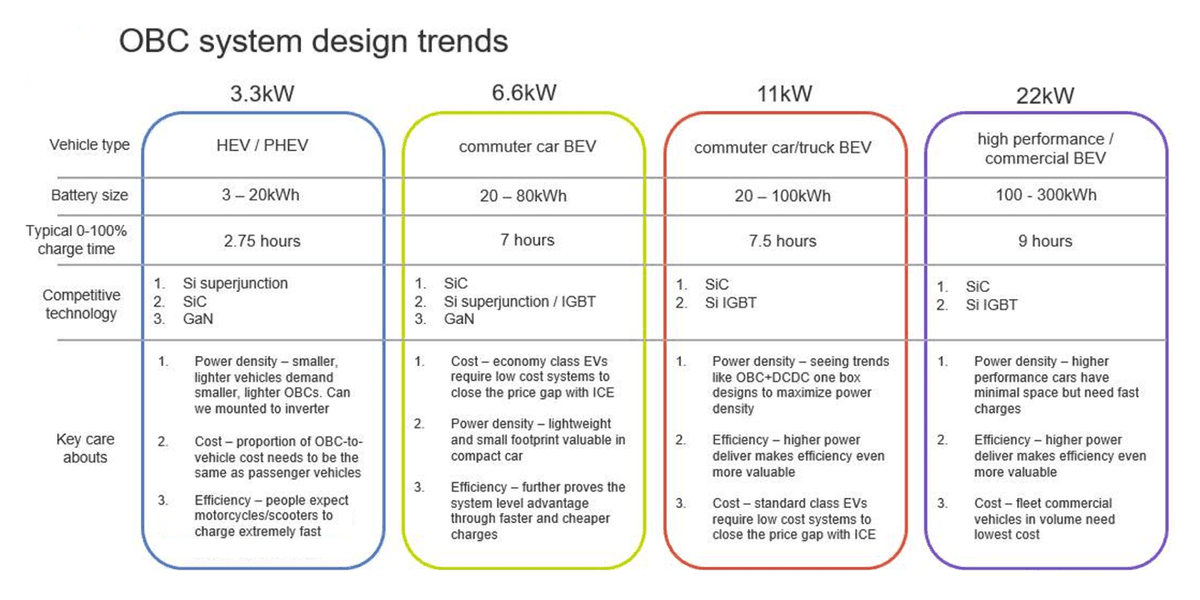
Vehicle types range from commuter car BEVs to larger and higher-performance BEVs such as e-trucks. As shown in the image, even with more than 3× the charging power, the larger-capacity vehicles may still have a larger 0% to 100% charge time. This makes OBCs especially efficient for high-power systems; that is, less power is wasted and a quicker charge is obtained.
Outside of OBC efficiency, parameters such as cost, weight, and size are critical where smaller, lighter OBCs can be more readily implemented in a vehicle, often with a tight space budget. Additionally, OBC cost for both the consumer and for the OEM directly impacts the capex/bottom line of the manufacturer and the ease of accessibility for the consumer. In order to stay competitive, the OBC must help the EV meet the price point of ICE-based vehicles. Use reference designs for 6.6 kW Bi-Directional Totem-Pole PFC and CLLC, optimized for energy efficiency and 6.6 kW Bi-Directional Totem-Pole PFC and CLLC, optimized for power density, to streamline your system design.
22kW bidirectional OBC designs: Si vs. SiC sample design
Benefits of bidirectional power flow
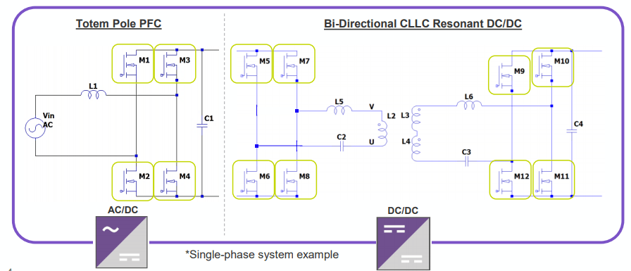
As stated in our earlier unidirectional OBC design piece, bidirectional chargers can inherently achieve higher efficiencies than unidirectional designs due to the omission of the diode losses. The unidirectional DC/DC block includes the use of the Vienna PFC diode, while the unidirectional LLC resonant converter accomplishes output rectification with a diode bridge. Figure 2 shows the typical skeleton of a single-phase bidirectional OBC — the full-bridge rectifier has been replaced with low-loss SiC MOSFETs to eliminate the losses resulting from the forward voltage drop of the rectifier diodes. This, in turn, reduces power dissipation, thereby simplifying thermal management requirements.
While the Asia-Pacific (APAC) is leading the bidirectional charging initiative for EVs, there is a general trend toward the employment of bidirectional OBCs for their higher system efficiency as well as the potential for V2-other applications, including vehicle-to-home (V2H) power generation, vehicle-to-grid (V2G) opportunities, and vehicle-to-vehicle (V2V) charging use cases (such as jumpstarting another EV).
22-kW bidirectional OBCs: Si vs. SiC
As shown previously in Figure 1, Si-based bidirectional OBCs with Si superjunction technologies and Si-based IGBTs are the primary contenders against SiC bidirectional OBCs. However, this section illuminates how SiC exceeds these technologies in all relevant aspects (cost, size, weight, power density, efficiency). Let’s begin by looking at Figure 3, which displays a reference schematic for both a Si- and SiC-based 22-kW bidirectional OBC, showing a side-by-side comparison in the number of power devices and gate drivers.
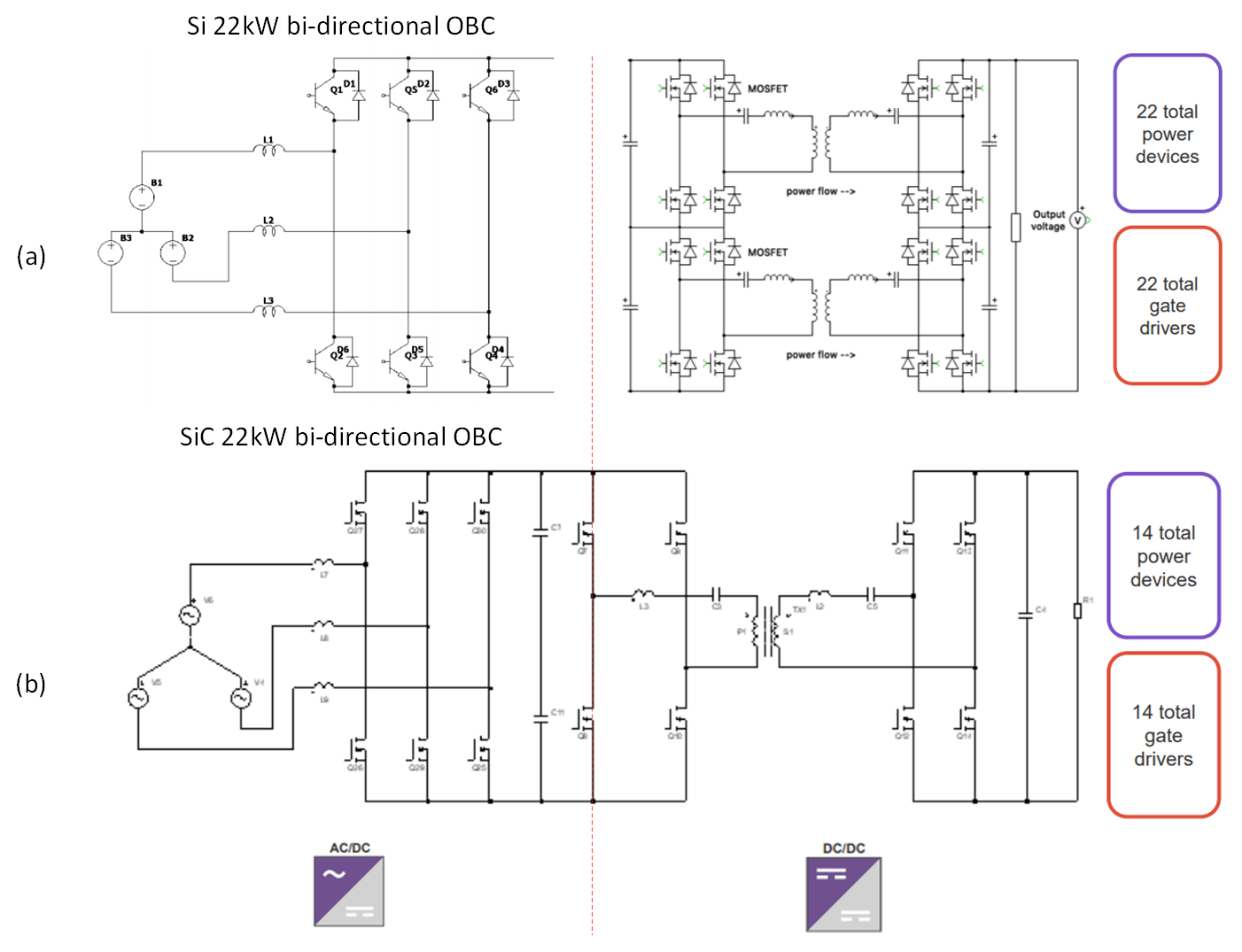
Table 2 lists the respective specifications of the first, AC/DC totem-pole PFC stage and the second, DC/DC bidirectional CLLC resonant stages. From both the image and the table, it can be readily seen that there is both over a 30% decrease in power device and gate drivers from the Si design to the SiC design, with the additional benefit of more than double the switching frequency. This leads to a reduced component size, weight, and cost of the power conversion system altogether, all while operating at a greater efficiency. Reference designs for 22 kW Bi-Directional CLLC and 22 kW Bi-Directional Active Front End (AFE) can get you started with bi-directional on-board charger system design.
Table 2
22kw Bi-directional OBC: Si vs SiC
Si-based AC/DC Totel Pole PFC Specs | |
|---|---|
Vin | 90-277 VAC (1-phase) 304-504 VAC (3-phase) |
Power Devices | 8 × Si IGBT |
Fs | 20 kHz |
DC/DC Converter Specs | |
Vin (DC Link Voltage) | 380-425 V |
Vout | 480-800V |
Power Devices | 16 × 650V Si SJ MOSFET |
Fs | 80-120 kHz |
SiC-based AC/DC Totel Pole PFC Specs | |
|---|---|
Vin | 90-277 VAC (1-phase) 304-504 VAC (3-phase) |
Power Devices | 6 × E3M0032120x |
Fs | 45 kHz |
DC/DC Converter Specs | |
Vin (DC Link Voltage) | 380-900 V |
Vout | 200-800V |
Power Devices | 8 × E3M0032120x |
Fs | 140-250 kHz |
Cost savings are further broken down in Figure 4 with a system cost breakdown for the Si and SiC systems. The Si system is nearly 20% more than SiC — this is largely due to the comparatively large amount of gate drivers and magnetics in the DC/DC block. So while it can be argued that discrete SiC-based power devices are relatively more expensive than individual Si-based diodes and power transistors, when employed within a system, the capabilities of SiC devices allows for less to be leveraged, therefore cutting down on costs of circuit components required to support the various power device functions.
Beyond cost savings, the SiC system is able to yield a peak system efficiency of 97% with a power density of 3 kW/L, while the Si OBC accomplishes a 95% efficiency with a power density of only 2 kW/L. This increase in system efficiency could add an annual energy savings of, on average, $40.00 to the consumer.
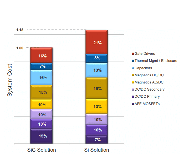
Table 3 compares costs, power density, operational savings, and CO2-based savings between Si and SiC implementations of both a 6.6-kW and 22-kW bidirectional OBC. The savings become much more pronounced the higher up the power spectrum an OBC goes. Both the 6.6-kW and 22-kW bidirectional SiC-based OBCs have a lower BOM cost, ultimately lowering the system cost for the OEM. When combined with the operational savings and the SiC-drive CO2 savings, the savings trickle down to the consumer, thereby closing the price gap with ICE-based solutions while also helping to lower emissions for the planet.
Table 3: SiC system advantages.
System Advantage of 6.6kW bi-direct. | ||
|---|---|---|
Si | SiC | |
System cost savings enclosure, thermal, magnetics, capacitors | 100% | 98% <$5 |
Power Density OEM-specific $/liter | >2kW/L | <3kW/L |
System Efficiency (Operational Savings) 0.55k (0.43)Wh/100km × 30,000km.y × $72/t | 94.5% ./. | 97% $22/year |
SiC-driven CO2 Savings 300k km lifetime × 400g/kWH, 0.44 (0.43)kWh/100km × $72/t | ./. | $26 |
SiC-driven Net Lifetime Savings (system cost savings + operational savings + CO2 savings) | ./. | ~$355 |
System Advantage of 22kW bi-direct. | ||
|---|---|---|
Si | SiC | |
System cost savings enclosure, thermal, magnetics, capacitors | 100% | 82% >$30 |
Power Density OEM-specific $/liter | ca.2kW/L | ca.3kW/L |
System Efficiency (Operational Savings) 0.55k (0.43)Wh/100km × 30,000km.y × $72/t | 95% ./. | 97% $32/year |
SiC-driven CO2 Savings 300k km lifetime × 400g/kWH, 0.44 (0.43)kWh/100km × $72/t | ./. | $38 |
SiC-driven Net Lifetime Savings (system cost savings + operational savings + CO2 savings) | ./. | ~$550 |
Wolfspeed’s expertise in SiC
Wolfspeed’s 30-year-plus legacy in the design and development of SiC components and systems helps lower barriers for a designer to employ highly desirable SiC-based components in their next OBC. The combination of Wolfspeed’s broad selection of SiC power devices, SiC systems, and expertise allows for the rapid development of robust design topologies that function reliably in the field. Complete bidirectional OBCs are already available in the Wolfspeed product portfolio along with individual AC/DC and DC/DC stages. This includes a 6.6-kW bidirectional OBC with a 97% system efficiency and 22-kW bidirectional OBC AC/DC and DC/DC converter blocks that can achieve efficiencies as high as 98.6% (Figure 5).
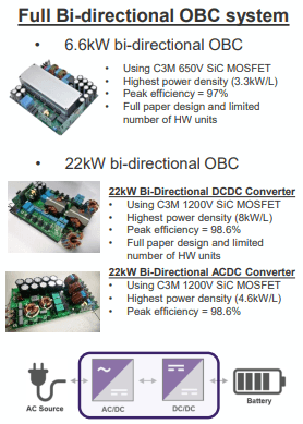
From a full product portfolio to exhaustive engineering and applications support with an online simulation platform and industry experts, Wolfspeed offers a comprehensive foundation for the design and development of SiC systems. This is extended to SiC-based OBCs wherein OEMS can leverage the highly desirable aspects in their next design while cutting on cost, passing the savings from BOM cost and efficiency design down to the customer.